BradsRoxor
Member
- Joined
- Aug 2, 2018
- Messages
- 47
- Points
- 8
- Location
- Springfield, MO, USA
- Roxor #
- 1426
- Roxor Ownership
- Roxor Owner
Have a gauge install post.
First image is the Autometer Gauge and temperature sender adaptor m12 X 1.5 part numbers. These are Phantom II gauges.
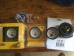
Image 2 shows most of the parts ready to be installed. You will need a glowshift oil filter sandwich adapter for the oil pressure sender to screw into. These have 4 ports so you could run oil pressure and oil temp gauges off this. YouTube has a video showing how to install this.
You will have to drill out the M12 X 1.5 adaptor. The water temperature sender won’t fit otherwise.
The probe is a bit smaller than the threads so I put it in a vice, eyeballed the appropriate bit and drilled the hole. And it worked! Now you can thread the temp probe into the adaptor. This adaptor and water temp sender (now one unit) screws into the thermostat housing on the left side. There is a plug you unscrew, and you screw your new water temp sender assembly into this hole.
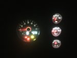
Wiring: I wired all positive and negative terminals together on the gauges (for the LED backlights and power to the gauges). I used a fuse tap on the instrument panel circuit behind the dash to get power when the ignition switch is turned on. The gauges are lit when the ignition is on.
Negative lead was run thru one of the grommets on the firewall to the negative post with a nut mounted to the firewall under the hood.
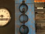
2” hole saw was used after carefully measuring the gauge spacing. YOU HAVE A 1” lip on the top where the dash bolts up!! Look at the top line on the tape!!
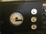
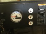
Gauges should pop right in! I think I achieved a good stock look...
Enjoy!!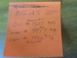


